POWER SUPPLY (5A Constant Current Source)

Contents
1
Introduction..................................................................................................................
2
System Design..............................................................................................................
2.1
PART I.................................................................................................................
2.2
PART II................................................................................................................
2.3
555 Timer
Circuit..................................................................................................
3
Final Design.................................................................................................................
1
Introduction
Most electronics require regulated power. When a power
supply changes the voltage and type of power, the result is not always a steady
output. Though it does not turn on and off completely, fluctuations in the
outcoming voltage still occur without regulation. An unregulated power supply
can deliver more power than expected. Such a surge fed to delicate
electronics like computers and televisions could
cause severe damage
to the parts or even
permanent harm that could cause damage beyond repair.
The added function
of regulating power increases the cost of the device,
but it can save you the
price of having to purchase new electronics to replace those ruined by unregulated voltage overwhelming them. To save money while powering
devices with loads that
closely match the power supply’s
output use unregulated power supplies. But electronics require regulated power.
Don’t make the mistake of selecting the wrong supply.
Power supplies have essential functions found in all
models with additional operations added depending on the device
type. Power supplies
may need to change voltage
up or down, convert
power to direct
current, or regulate
power for smoother
outcoming voltage. These
functions will help you choose which supply you need for your electrical needs.
The goal of this project is to build a power supply with a high current at load, which produces high thermal energy and can be
controlled with the help of a knob. The output current can also be turned off
after a certain amount of time. PWM is used to control the ON time of the circuit
which also can be changed
according to requirements. To achieve the goal different types of circuits were
implemented and tested. As shown in the figure below load on the left is 0.980 ohms
and right is 0.45 ohms

2
System Design
Main Circuit
The idea of a Linear power supply is used to design the
circuit to achieve a goal a linear voltage regulator is used alongside a
transistor to produce the current across the load. The load resistance was
measured, and it was found that it was .980 ohms approx. 1 ohms. So, the
circuit was designed to obtain the 5A current across a 1-ohm load.
To get 5 ohms across a 1 ohms load a constant 5V is
necessary so a linear voltage regulator is used LM7805 which can provide a
constant 5 V regulated.
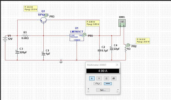
Figure 1: Prototype 1
As shown in the figure above we were able to get the 5-ampere current
across a load of 1 ohm. Instead of TIP42, MJ2955 is used since they have the same
attributes and MJ2955 is
more common.
Later the load was
changed and reduced to 0.45 ohms. If the
same circuit is used there would be more current
across the load and can blow up the load. So, the new circuit
was designed so that where current can be changed accordingly.

Figure 2: Prototype 2
As shown in Figure 2, there is a constant output current
of 5 A across the load of 0.45 ohms. Using the R6 the current across the load
can be changed. TIP 2955G and 2N3055A are used as a current source. This prototype also has a diode for the
current protection which is D1 as shown in Figure 2.
555 timer is used as PWM to keep the circuit ON for the desired amount
of time. In 555,
with the right value of the capacitor and resistor, the ON time can be changed as per requirement.

Figure 3: Timer
Circuit
As shown in Figure 3, R2 and C1 can be changed to get
the ON timing of the circuit. When the S1 key is pressed the LED 1 will be on for “T” seconds, and will go off automatically
after T seconds. So, in general terms, it
is a monostable multivibrator, which can be calculated using the formula
below.
T= 1.1 * C1 *R2
3
Final Design
For the final
design Prototype II is used alongside the 555 timer.

Figure 4: Final
Circuit
Both circuits were combined as shown in Figure 4 and PCB was printed. For the 12 V source, a switch mode regulator was used which can be directly plugged into the mains.

Figure 5: PCB board of the circuit
The figure
shows the final board printed
using the Milling
machine.
 |
Figure 6: Final Product
Figure 6 shows the final
product of the project. In the left figure, there is an LED as an indicator, a knob to change the output current,
and a Push button
on the top. On the right, there is an outlet to connect the load.

Comments
Post a Comment